Table of Contents
2 Number Systems
2.1 Types of Number Systems
In the previous chapter, we had a look at the way a processor (and a computer) can deal with the digital values '$0$' and '$1$'. However, we haven't seen how the processor can handle larger numbers. To approach this, first a short historical outline is shown.
2.1.1 Addition Systems
The first used number system was the addition system. These are also still in use: when enjoying a German beer in the beer garden the waiter is counting the 'progress' by dropping dashes onto the coaster (see figure 1)

In ancient Rome, these systems were deeper elaborated. Different symbols represent numbers of various sizes:
- $\rm I = 1$
- $\rm V = 5$
- $\rm X = 10$
- $\rm L = 50$
- $\rm C = 100$
- $\rm D = 500$
- $\rm M = 1000$
Besides this representation of quantities also the position of the symbol in the numeral was important:
- In general: the letters have to be arranged decreasing from left to right. For example $\rm MDCI = 1601$
- There are deviations of this rule: When up to three of the lower symbols are written to the left, these have to be subtracted. Sounds complicated?
A kind of…. for example $\rm \color{blue}{M}\color{green}{CCD}\color{red}{L}IV = \color{blue}{1}\color{green}{3}\color{red}{5}4$.
Luckily, we do not have to learn this, but by this trick, the length of the numeral could be shortened,
It becomes even more complicated when trying to calculate with the numbers: what is the result of the multiplication $\rm CCMXXXVII \cdot DDDIIX$?
2.1.2 Decimal and Binary
Luckily, we have nowadays a better system for writing numbers: the positional system.
We 'just know' what a number like $23$ means. However, for understanding how the computer works we have to investigate this gut feeling and put some technical terms onto it.
- We are accustomed to counting with our fingers from $1$ to $10$. For this, we have 10 symbols to count: $0,1,2,3,4,5,6,7,8,9$. This group of distinguishable symbols is called digits.
- The amount of the digits is called base $B$. We are used to the decimal base $B=10$, in logic we used binary (also called dual) $B=2$.
- When we count beyond the maximum number we are used to 'enlarge the number to the left': after the $9$, we count $10$. But the digit $1$ in $10$ is more worth than the $1$ in $31$ (of course). It is on a different position, on the position of the tens.
- Each position gets numbered: the ones count 0, the tens 1, the hundreds 2, the thousands 3, and so on. This 'position number' is called index $i$.
- Knowing the index, also the 'worth of the position' can be derived: the place factor $p$ (like one, ten, hundred) can be calculated with the base and the index: $p=B^i$.
- A numeral as a group of digits represents what is commonly known as a number.
- A code or encoding means a way to translate one way to display information into another. E.g. A decimal numeral into a Binary, or an idea of an algorithm into a computer language.
To recapitulate this for $B=10$ we will calculate the amount of a decimal numeral here once in detail (click on the arrow to the right “>” to see the next step, alternatively see here):
Ok, that was simple. But what about a binary number? Let's calculate the amount of a binary numeral:
So, what did we find out?
- The shown process is a relatively simple way to convert binary numerals to decimals.
- A 8-digit binary numeral is equal to 3 digit decimal numeral. $\rightarrow$ Numerals in binary become lengthy
Therefore, it would be better to have a more structured way of presenting the numerals which are used in the processor. Internally, the processor just knows 0's and 1's. But investigating a huge bunch of these (e.g. when analyzing the internal memory or a file) is not catchy in order to understand anything.
The first step is to group the bits:
- 4 bits are called a nibble (the name derives from 'to bit' and 'to nibble')
- 8 bits are called a byte
- 16 bits are (usually) called a word. In detail, this depends on the processor.
- 32 bits are (usually) called a double word. Like the word this also depends on the processor.
By this, one can separate parts of information (e.g. in a file) better. It is also important to mark the order of the bits. For decimal numerals like $42$ the rightmost digit has always the lowest value. The technical term for the 'lowest value' in a binary numeral is called lowest significant bit or LSB. When the LSB is on position 0 (= rightmost) this order is called LSB 0. This was used in the calculation above and is commonly used. In some cases (some memory setup and communication protocols) the order is just the other way around. In this case, the most significant bit is on position 0. This order is therefore called MSB 0. Example: $3_{10} = 0000\;0011_{2}\text{ (LSB 0)}$, $3_{10} = 1100\;0000_{2}\text{ (MSB 0)}$
What is still missing are expressions for large amounts of data. We can describe these using prefixes and the powers of two. You may already know the prefixes such as kilo and mega, but it is worth brushing up on the powers of two. The easiest way to illustrate this is with a chessboard. Maybe you know the legend of the inventor of the chessboard, who was granted a wish by the king. His wish was that the king would give him one grain of rice on the first chessboard square and every time twice as much on each subsequent square. We'll play through this briefly, here to write down the powers of two:
- in the first square we enter two to the power of 0, which results in 1.
- In the second square, two to the power of 1, resulting in two.
- Then 4, 8, 16, 32, 64, 128, 256, 512, and then in the next line two to the power of ten, resulting in 1024.
You should definitely remember this sequence of the values for the power of 2! They are not only important for the exam, but also for the following semesters and computer science.
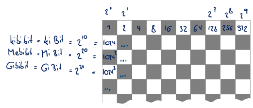
1024 bit is also called kbit or kilobit in the semiconductor industry. You will notice here that the kilo is slightly more than 1000. To make it easier to distinguish, according to the ISO or ECE standard, you should say kibi instead of “kilo” and write kibibit. The same applies to 2^20, i.e. 1024 to the power of two: megabit has become common there. However, mebibit, should be used to differentiate. The nomenclature continues in the same way for 2^30 and 2^40: gibibit and tebibit.
2.1.3 Other bases
When looking at multiple bases, it is important to clearly mark the base of the numerals.
Already in the chapter before a numeral like $110$ could either be $110$ in decimal or $110$ in binary, which is $6$ in decimal.
In the following the base will be written as a subscript: $110_2 = 6_{10}$.
At the end of this subchapter, we will also see other ways to mark the base.
Hexadecimal
With the ideas of the previous subchapter, we already can structure the bits. In order not to use the lengthy binary presentation it is common to use other bases. One important base is $16$ for hexadecimal numerals. There, we need 16 distinguishable symbols: $0, 1, 2, 3, 4, 5, 6, 7, 8, 9, \rm A, B, C, D, E, F$. With these digits, it is possible to encode (=rewrite by other means) exactly 4 bits or one nibble. The encoding will be as follows:
| Dual | Decimal | Hexadecimal |
|---|---|---|
| $0000_2$ | $0_{10}$ | $0_{16}$ |
| $0001_2$ | $1_{10}$ | $1_{16}$ |
| $0010_2$ | $2_{10}$ | $2_{16}$ |
| $0011_2$ | $3_{10}$ | $3_{16}$ |
| $0100_2$ | $4_{10}$ | $4_{16}$ |
| $0101_2$ | $5_{10}$ | $5_{16}$ |
| $0110_2$ | $6_{10}$ | $6_{16}$ |
| $0111_2$ | $7_{10}$ | $7_{16}$ |
| $1000_2$ | $8_{10}$ | $8_{16}$ |
| $1001_2$ | $9_{10}$ | $9_{16}$ |
| $1010_2$ | $10_{10}$ | $\rm A_{16}$ |
| $1011_2$ | $11_{10}$ | $\rm B_{16}$ |
| $1100_2$ | $12_{10}$ | $\rm C_{16}$ |
| $1101_2$ | $13_{10}$ | $\rm D_{16}$ |
| $1110_2$ | $14_{10}$ | $\rm E_{16}$ |
| $1111_2$ | $15_{10}$ | $\rm F_{16}$ |
This directly reduces the necessary amount of digits to show data.
The hexadecimal representation is for example used in the file type *.hex.
This is the output file of an embedded c compiler and contains code in a machine-readable representation.
An example of a c code and its hex file is shown in figure 3.
In the hex file the bytes (= 2 nibbles = 2 digits) are visibly grouped.


The bytes in the first line are:
| Byte0 | Byte1 | Byte2 | Byte3 | Byte4 | Byte5 | … |
|---|---|---|---|---|---|---|
| $10_{16}$ | $00_{16}$ | $00_{16}$ | $00_{16}$ | $19_{16}$ | $\rm C0_{16}$ | … |
But what is the decimal value of these numerals?
This transfer is also possible in the process shown in 2.1.1:
$ Z_{10}=\sum_{i=-n}^m z_i \cdot B^i$, where $z_i$ is the digit on position i.
As an example the Byte4 shall be written in decimal:
$ Z_{10}({\rm Byte}4)= Z_{10}(19_{16}) \\ =\sum_{i=0}^1 z_i \cdot 16^i = \\ 1 \cdot 16^1 + 9 \cdot 16^0 = 16 + 9 = 25_{10}$
Octal
Another - much less common - base is 8. This number system is called octal. In this case, only $0,1,2,3,4,5,6,7$ can be used for digits.
Similar to the number systems before, the following formula applies for the transfer in decimal: $ Z_{8}(X)= \sum_{i=-n}^m z_i \cdot 8^i$
2.1.4 From decimal to other bases
Fast Approach: Try and Subtract
Up to this point chapter, we only have converted other $B$-based numerals to decimal.
Now we want to try to convert a decimal into hexadecimal, for example, the numeral $315_{10}$.
One way is to first convert to binary by “try and subtract” and then convert the nibbles into hexadecimal:
For this example, we first try to subtract the highest power of 2, which not results in a negative number. \begin{align*} 315_{10} &- 256_{10} &= 59_{10} \quad \quad 2^8\quad \\ 59_{10} &-32_{10} &= 27_{10} \quad \quad 2^5\quad \\ 27_{10} &-16_{10} &= 11_{10} \quad \quad 2^4\quad \\ 11_{10} &-8_{10} &= 3_{10} \quad \quad 2^3\quad \\ 3_{10} &-2_{10} &= 1_{10} \quad \quad 2^1\quad \\ 1_{10} &-1_{10} &= 0_{10} \quad \quad 2^0\quad \\ \end{align*}
The number $315_{10}$ is similar to $2^8 + 2^5 + 2^4 + 2^3 + 2^1 + 2^0$. This is equal to $100111011_2$ or $0001\;0011\;1011_2$. For the hexadecimal value, these nibbles have to be converted, which leads to $13B_{16}$. This is often the fastest way but is based on the constraint, that one remembers the power of 2.
Works every time: Repeated Division / Multiplication
But how can we convert a decimal numeral like $452.12_{10}$ e.g. to hexadecimal?
The easiest way is to at first separate the value in integer decimal $z$ and decimal places $f$:
$452.12 \rightarrow z = 452 , f = 0.12$
1. handling the integer decimal
The integer decimal $z$ can be converted by the abovementioned method. A different way is via repeatedly dividing by the base (here $B=16$) and using the remainder:

For each of the shown steps, the integer of the division of the step before is used ($28$, $1$).
The last steps (and any following) result in a remainder of $0$.
For hexadecimal numerals, we have to focus on the remainder from below to top and convert the value into hexadecimal digits
| each position in decimal | $\color{red}{1}$ | $\color{green}{12}$ | $\color{blue}{4}$ |
|---|---|---|---|
| each position in hexadecimal | $\color{red}{1}$ | $\color{green}{\rm C}$ | $\color{blue}{4}$ |
The result is $\color{red}{1}\color{green}{\rm C}\color{blue}{4}_{16}$
2. handling the decimal places
The decimal places $0.12$ can be converted by repeatedly multiplying by the base (here $B=16$) and using the integer:

For each of the shown steps, the decimal places of the multiplication of the step before are used ($.92 \rightarrow .72 \rightarrow .52 \rightarrow .32 \rightarrow .12 \rightarrow .92$ ).
The decimal place in the second last line is equal to the first one. Therefore also any further places will also be equal. That leads to repeating decimals.
For hexadecimal numerals, we have to focus on the integer from top to below and convert the value into hexadecimal digits.
| each position in decimal | $\color{blue }{1}$ | $\color{green}{14}$ | $\color{brown}{11}$ | $\color{red }{8}$ | $\color{grey }{5}$ | $\color{blue }{1}$ | $\color{green}{14}$ | $...$ |
|---|---|---|---|---|---|---|---|---|
| each position in hexadecimal | $\color{blue }{1}$ | $\color{green}{\rm E}$ | $\color{brown}{\rm B}$ | $\color{red }{8}$ | $\color{grey }{5}$ | $\color{blue }{1}$ | $\color{green}{\rm E}$ |
The result is $\rm 0.\overline{ \color{blue }{1} \color{green}{E} \color{brown}{B} \color{red }{8} \color{grey }{5} }$
Results:
- A decimal numeral has to be separated into integer decimal and decimal places.
- By dividing/multiplying with the base the integer decimal / decimal places can be converted to another base. This works for all other bases like $2$ or $8$.
- The results have to be converted (at least for the base $\rm B > 10$, like hexadecimal).
- A small decimal place can lead to longer (or even infinite) numerals in another base.
Especially the last result has a major impact on calculations on microcontrollers and computers:
The internal logic is only based on binary, which also shows this problem. However, the internal memory for a numeral is limited.
Even when stored in 32bit - it is not possible to exactly convert the $0.12_{10}$ to binary. In the following table, the $n$-bit equivalent of $0.12_{10}$ in the binary and hexadecimal system is shown. Additionally, this value is also re-converted to a decimal numeral.
| number of bits $n$ | number system | numeral |
|---|---|---|
| $8 $ | binary | $0.0001\; 1111_2 $ |
| hex | $\rm 0.1F_{16} $ | |
| equiv. dec | $0.12109375_{10} $ | |
| $16 $ | binary | $0.0001\; 1110\; 1011\; 1000_2 $ |
| hex | $\rm 0.1EB8_{16} $ | |
| equiv. dec | $0.11999511718_{10} $ | |
| $24 $ | binary | $0.0001\; 1110\; 1011\; 1000\; 0101\; 0010_2 $ |
| hex | $\rm 0.1EB851_{16} $ | |
| equiv. dec | $0.11999994516..._{10}$ | |
| $32 $ | binary | $0.0001\; 1110\; 1011\; 1000\; 0101\; 0001\; 1110\; 1100_2$ |
| hex | $\rm 0.1EB851EC_{16} $ | |
| equiv. dec | $0.12000000011..._{10}$ |
This might seem like a little issue. But there are a lot of areas, where exact decimal places are mandatory, like banking, or simulations.
This situation even arises, when using floating point representation - the principal problem is also nicely explained in this clip.
2.1.5 Binary Coded Decimals
The first approach to this was the development of Binary Coded Decimals.
The encoding algorithm from a decimal numeral into BCD is simple: “don't use the division/multiplication method mentioned before - just take the same hexadecimal digit on each decimal position like the decimal one” .
This means the decimal numeral $391.21_{10}$ is encoded to $391.21_{\rm BCD}$. Inside the processor, each digit is handled as a hexadecimal number: $3\;9\;1\;.\;2\;1_{\rm BCD}$ equals $0011\;1001\;0001\;.\;0010\;0001_{2}$.
The main disadvantage is the ineffective storage management and more complex algorithms for addition, subtraction, and so on.
2.1.6 Marking the base of a numeral
Up to here, the marking was done by the subscript. Postfixes cannot be used in the software development environment, and sometimes are also not used in datasheets. Alternative ways for marking are the following:
| base | subscripted (mathematically) | prefixed (in code) | postfixed | further marking |
|---|---|---|---|---|
| 2 (binary) | $0010 1010_2$ | 0b00101010 | 00101010B | $\%00101010$, 00101010b |
| 10 (decimal) | $1027_{10}$ | 1027 | 1027D | - |
| 8 (octal) | $1027_{8}$ | 01027 | 1027O | - |
| 8 (hexadecimal) | $\rm 27D_{16}$ | 0x27D | 27H | $27, 27h |
Be aware, that in the code 01027 is not equal to 1027!
When to use which base?
When programming code for an embedded system, the system will always see 0's and 1's after compiling.
So, the microprocessor does not have to be considered.
In some cases, on the other hand, the binary or hexadecimal numeral is much more convenient to read:
Here is an example, where the binary numeral shows a smiley (e.g. for writing this on the screen), but the hexadecimal (or decimal) value does not give a clue what the output will be:

2.2 basic arithmetic operations in binary and hexadecimal
In this subchapter, we will have a look at the way how the arithmetic operations have to be executed manually in other bases. For math, it does not matter in which number system one calculates: a calculation like $2_{10} + 5_{10} = 7_{10}$, will be in binary $0010_2 + 0101_2 = 0111_2$. The values behind the numerals are still the same, they are only encoded differently.
The execution is similar to the well-known experience of calculating in the decimal system.
Important for all of the operations: Never forget the carry!
Just a small reminder in decimal:
\begin{align*} \color{white}{+}192 \\ +378 \\ +672 \\ \hline 1\overset{\color{red}{2}}{2}\overset{\color{red}{1}}{4}\overset{}{2} \end{align*}
The red numbers are the carry-over of the calculation to the right. If a calculation exceeds the limits of the base, a new digit is added and the carry is taken into account in it. A similar carry will happen in the next subchapters.
2.2.1 Addition
In Binary
The following examples shall show the concept of binary:
\begin{align*} \begin{array}{lll} { a) \\ \color{white}{+}0_2 \\ +0_2\\ \,\overline{\color{white}{+}\overset{}{0_2}} }&{ b) \\ \color{white}{+}0_2 \\ +1_2\\ \,\overline{\color{white}{+}\overset{}{1_2}} }&{ c) \\ \color{white}{+}1_2 \\ +0_2\\ \,\overline{\color{white}{+}\overset{}{1_2}} }&{ d) \\ \color{white}{+}1_2 \\ +1_2\\ \;\;\overline{\overset{\color{red}{1}}{1}\overset{}{0_2}} } \end{array} \end{align*}
The four simplest examples show the carry only for $d) \quad 1_2 + 1_2$.
Now we can also connect the number system with the logic gates! The addends are called $A$ and $B$ (e.g. $A=1_2$, $B=1_2$), the sum is the numeral $CS_2$ (e.g. $C=1$, $S=0 \rightarrow CS_2=10_2$).
When analyzing the calculations above, we need one logic gate for $S$, which only results in $1$, when either $A=1$ or $B=1$: this is the XOR gate.
For the carry $C$ we only get $1$, when both of the inputs are one: Here an AND gate has to be used.
The figure 4 shows the resulting logic. This is also called a half-adder.
The next step shall be a bit more complicated - or better: some bit more complicated. We want to do the calculation $A + B = 0011_2 + 0111_2$.
\begin{align*} \color{white}{+}\,00\boldsymbol{1}1_2 \\ +01\boldsymbol{1}1_2\\ \,\overline{\color{white}{+}\overset{\color{red}{1}}{1}\overset{\color{red}{1}}{0}\overset{\color{red}{\boldsymbol{1}}}{\boldsymbol{1}}\overset{}{0_2}} \end{align*}
The rightmost, first step is easy since we already had this in the examples before. The next step (marked in bold) is differing: not only do we have to consider the digits from $A$ and $B$, but also the carry from the calculation before. The carry from before has to be added for all the next steps similarly.
For the calculation by hand, we did four individual additions from the right to the left. The processor has to do the same. But first, we have to expand the half-adder. For a complete addition step, we need a logic with the inputs $A$, and $B$ and carry from the step before $Cin$. The output will be still $S$ and $C$.
In figure 5 the full adder is shown. It is an alternative representation from what we have done for calculation by hand:
- first add one bit from $A$ to one bit from $B$ (half adder). The result is in $S'$ and $C'$.
- Then, take the result $S'$ and add it with $Cin$ (second half adder). The result is in $S$ and $C''$. $C$ is already the wanted output.
- For the carry output we need to consider both carries $C'$ and $C''$. When two or all of the inputs $A$, $B$, and $Cin$ are high, then the carry has to be set to high. This can be implemented with $C'$ OR $C''$.
This full adder can now be stacked together to add multiple bits $A0, A1, ...$ to $B0, B1; ...$.
In Hexadecimal
The calculation in hexadecimal is conceptually the same. Some examples, which we will discuss below:
\begin{align*} \begin{array}{lll} {a) \\ \color{white} {+}5_{16} \\ + 3_{16}\\ \,\overline{\color{white}{+}\overset{}{8_{16}}} }&{ b) \\ \color{white} {+}7_{16} \\ + 3_{16}\\ \,\overline{\color{white}{+}\overset{}{\rm A_{16}}} }&{ c) \\ \color{white} {+}\, 1_{16} \\ + {\rm D}_{16}\\ \,\overline{\color{white}{+}\overset{}{{\rm E}_{16}}} }&{ d) \\ \color{white} {+} {\rm E}_{16} \\ + {\rm A}_{16}\\ \;\;\overline{\overset{\color{red}{1}}{1}\overset{}{8_{16}}} } \end{array} \end{align*}
a) This one is simple: looks like a decimal formula..
b) Here, the summands look like decimal numerals, but the result $7_{10} + 3_{10} = 10_{10}$ is still within the range of the base. The correct symbol would be $10_{10} = \rm A_{16}$
c) Now, the summands are a “bit more hexadecimally”. The easiest way is: “convert the single digit from hex to decimal, do the operation, and re-convert to hex”. For the given example: $1_{10} + 13_{10} = 14_{10} = \rm D_{16}$
d) Also for this calculation the described way is beneficial: $\rm E_{16} + A_{16} = 14_{10} + 10_{10} = 24_{10}$. The result is larger than the base, and therefore the value has to be separated in more digits: $24_{10} = 16_{10} + 8_{10} = 10_{16} + 8_{16} = 18_{10}$
For a hexadecimal value with more digits, the carry of the calculation before has to be added - otherwise, every step remains the same.
2.2.2 Subtraction
In Binary
The following examples shall show the concept of binary:
\begin{align*} \begin{array}{lll} { a) \\ \color{white} {-}0_2 \\ - 0_2 \\ \,\overline{\color{white}{-}\overset{}{0_2}} }&{ b) \\ \color{white} {-}1_2 \\ - 1_2 \\ \,\overline{\color{white}{-}\overset{}{0_2}} }&{ c) \\ \color{white} {-}1_2 \\ - 0_2 \\ \,\overline{\color{white}{-}\overset{}{1_2}} }&{ d) \\ \color{white} {-}0_2 \\ - 1_2 \\ \;\;\overline{\overset{\color{red}{1}}{\color{white}{0}}\overset{}{1_2}} } \end{array} \end{align*}
The calculation for $d)$ shows the carry, which here has to borrow a bit from the next upper digit. This is similar to the calculation: \begin{align*} \color{white} {-}42_{10} \\ - 23_{10}\\ \;\;\overline{\overset{\color{red}{1}}{1}\overset{}{ 9_{10}}} \end{align*}
With more digits the calculation in the binary system will look like the following:
\begin{align*} \color{white} {-}\,10\boldsymbol{1}0_2 \\ - 01\boldsymbol{1}1_2\\ \,\overline{\color{white}{+}\overset{\color{red}{1}}{0}\overset{\color{red}{1}}{0}\overset{\color{red}{\boldsymbol{1}}}{\boldsymbol{1}}\overset{}{1_2}} \end{align*}
In this example the bold column will be explained shortly:
\begin{align*} \color{white} {-}\,\boldsymbol{1}_2 \\ - \boldsymbol{1}_2\\ \overline{ \overset{\color{red}{1}} {\color{white}{0}} \overset{\color{red}{\boldsymbol{1}}} {\boldsymbol{1}}_2 } \end{align*}
The calculation has to be executed as follows: $\boldsymbol{1}_2 - (\boldsymbol{1}_2 + \color{red}{\small{\boldsymbol{1}}} ) = {\boldsymbol{1}}_2 $. Additionally, another carry has to be taken from the next digit.
In Hexadecimal
The calculation in hexadecimal is conceptually again the same. Some examples, which we will discuss below:
\begin{align*} \rm \begin{array}{lll} { a) \\ \color{white}{-}15_{16} \\ -\color{white}{1}3_{16} \\ \,\overline{\color{white}{-}\overset{}{12_{16}}} }&{ b) \\ \color{white}{-}23_{16} \\ -\color{white}{\rm B}6_{16} \\ \overline{\color{white}{-}\overset{\color{red}{1}}{1} {\rm D}_{16}} }&{ c) \\ \color{white}{-}3{\rm F}_{16} \\ -1{\rm A}_{16}\\ \color{white}{-}\overline{\color{white}{B}\overset{}{25_{16}}} }&{ d) \\ \color{white}{+}\,38_{16} \\ - 1{\rm A}_{16}\\ \color{white}{+}\overline{\overset{\color{red}{1}}{1}\overset{}{{\rm E}_{16}}} } \end{array} \end{align*}
a) This one is (again) simple: looks (again) like a decimal formula..
b) Here, both hexadecimal numerals look like decimal numerals, but the result $3_{10} - 6_{10} = 7_{10} + C$ lead to an underflow, where we have to take a carry of $C=-10_{10}$ for a decimal calculation. In hexadecimal, the carry differs. A better way to solve such a subtraction in hexadecimal is to add the carry before: $3_{16} - 6_{16} + \color{red}{10_{16}}$. Then the calculation can be converted to decimal: $3_{10} - 6_{10} + \color{red}{16_{10}} = 19_{10} - 6_{10} = 13_{10}$. This result has to be converted back to hexadecimal: $\rm 13_{10} = D_{16}$. For the next column, the carry has to be considered.
c) For this formula the idea from b) helps, too: for each digit-by-digit subtraction, we will have a look, at whether a transformation to decimal is beneficial. For the rightmost it is: $\rm F_{16}- A_{16} = 15_{10} - 10_{10} = 5_{10}$. The rightmost result is now: $5_{10} = 5_{16}$
d) We can do the same thing here, for $8_{16}-A_{16}$: consider the carry, convert to decimal, calculate, and re-convert to hexadecimal. $8_{10}-10_{10}+ \color{red}{16_{10}} = 24_{10}-10_{10}= 14_{10}$. The result is $\rm E_{16}$.
Note!
The subtraction within the processor is done a bit differently, with the two's complement. In short: the range of numerals will be divided in such a way that negative numbers can also be represented. By this, the subtraction can be transformed into an addition. It is roughly like transforming $10_{10} - 4_{10}$ into $10_{10} + (- 4)_{10}$.
2.2.3 Multiplication and Division
The multiplication table for binary is simple:
\begin{align*} 0_2\cdot 0_2 = 0_2 \\ 0_2\cdot 1_2 = 0_2 \\ 1_2\cdot 0_2 = 0_2 \\ 1_2\cdot 1_2 = 1_2 \end{align*}
Multiplication of longer binary numerals has to be executed similarly to decimal numerals:
\begin{align*} \begin{array}{lll} 1011_2 \cdot\, \color{blue}{1}\color{brown}{1}0\color{violet}{1}_2 \\ \hline \;\ \ \ \ \ \ \color{blue }{1011}\!\!\color{brown}{\downarrow}\;\,\color{violet}{\downarrow} \\ +\;\ \ \ \ \ \color{brown }{1011}\!\!\ \;\color{violet}{\downarrow} \\ +\;\ \ \ \ \ \ \ \ \ \color{violet}{1011} \\ \hline \ \ \ \ \ \overset{\color{red}{1}}{1}\overset{\color{red}{1}}{0}\overset{\color{red}{1}}{0}\overset{\color{red}{1}}{0}\overset{}{1}\overset{}{1}\overset{}{1}\overset{}{1}_2 \end{array} \end{align*}
The division is also relatively simple:
\begin{align*} 0_2 : 1_2 = 0_2 \\ 1_2 : 1_2 = 1_2 \end{align*}
With longer numerals it looks like the following:

related Links
- Conversion tool from decimal to hexadecimal, this tool shows also the steps and can be used vice versa
- The OmniCalculator can also calculate binary fractions and comes with another explaination of the manual process.
- A short video on the “Everything Formula” which prints all possible output and is directly related to binary encoding.
Exercises
Exercise 2.3.1. power tables


Exercise 2.3.2. Conversion to Binary
Convert the following hexadecimal numerals to the binary system.
Tip: Convert nibble by nibble to binary.
- $\rm 4321H$
- $\rm 0xCAFE$
- $ \$ $$\rm 4be79 $
- $ \$ $$\rm 398B4C $
- $\rm 0x3a4f.4ecd $
- $\$\rm 1.3DAF $
Exercise 2.3.3. Conversion to Hexadecimal and Decimal
Convert the following numerals from dual to hexadecimal and decimal numerals.
Tip: Use the numerals from Exercise 2.3.1.
- $\rm 0b10110110$
- $\%10100101$
- $\rm 1111\, 0111\, 0001\, 0011B$
- $\rm 0110111.0101b$
- $\rm 0.10101b$
- $\rm 0.1001\, 1001\, ... b$
Exercise 2.3.4. Conversion to Hexadecimal and Binary
Convert the following numerals from decimal to hexadecimal and dual numerals.
Tip: Use the numerals from Exercise 2.3.1.
- $123_{10}$
- $637_{10}$
- $1777_{10}$
- $8999_{10}$
- $41.4_{10}$
- $0.9_{10}$
- $11.3_{10}$
Exercise 2.3.5. Addition and Subtraction
Execute the following operations manually with the given dual numerals.
- $\rm 01110111B + 11010101B$
- $\rm 01011001B + 10011111B$
- $\rm 01100111B - 01001100B$
- $\rm 10101110B - 10000111B$
- $\rm 0011.111B - 0011.100B$
- $\rm 001111.011B + 1.010011B$
- $\rm 01101.100B - 01000.111B$
- $\rm 100101.11B - 110001.10B$
Exercise 2.3.6. Multiplication and Division
Execute the following operations manually with the given dual numerals.
- $\rm 1011B \cdot 0101B$
- $\rm 01100101B \cdot 110B$
- $\rm 10101111B : 101B$
- $\rm 11110000B : 1000B$
Exercise 2.3.7. Operation in Hex
Execute the following operations manually with the given dual numerals.
- $\rm 1334H + 07ABH$
- $\rm 0DC43H - 0BD19H$
- $\rm 1F23H + 90E8H$
- $\rm 98C5H - 84CAH$
- $\rm 234AH + 7EE6H$
- $\rm 0F10CH - 0ED43H$
Exercise 2.3.8. Further Questions
- Write down the decimal numeral for the first 4 hexadecimal places
- Which possible value range can be covered with an 8-bit variable?
Exercise 2.3.9. Two's Complement
In the simulation in figure 11 the two's complement of a 4bit value is shown.
On initialization, the value is the following:
- The value for variable $A$ is $1010_2 = 10_{10}$. The decimal value
10is also shown in the first display from the left in the circuit. - The value for variable $B$ is $1110_2 = 14_{10}$. The decimal value
14is also shown in the second display from the left in the circuit. - The addition $A+B$ leads to $S = 1000_2 = 8_{10}$. The decimal value
10is also shown on the rightmost display in the circuit. - There is another value in the second display from the right. This is called $B'$, and it is equal to $0010_2 = 2_{10}$.
- Why is
10+14=8? What happens to other values?
The input valuesAandBcan be changed by clicking on the bit values. - Try to analyze how
B' (shown in the brackets) is derived fromB. - Have a look at the wiki page of the Two's complement to understand how negative numbers are represented in a microcontroller.
What does the following representation show?

- Imagine that you have to rescue data from an old storage device. The interesting bits are given by the boxed area in figure 12. The bytes are LSB 0 oriented.
- What are these values in an unsigned integer?
- What are these values in signed integers based on the Two's complement?
Fig. 12: example for stored data in an EEPROM

From: Courbon F., Skorobogatov S., Woods C. (2017) Reverse Engineering Flash EEPROM Memories Using Scanning Electron Microscopy. In: Lemke-Rust K., Tunstall M. (eds) Smart Card Research and Advanced Applications. CARDIS 2016. Lecture Notes in Computer Science, vol 10146. Springer, Cham. https://doi.org/10.1007/978-3-319-54669-8_4